Categories
Uncategorized

Camshaft Correct break-in procedure !

 After the correct break-in lubricant is applied to the cam and lifters, fill the crankcase with fresh non-synthetic oil. Prime the oil system with a priming tool and an electric drill so that all oil passages and the oil filter are full of oil. Preset the ignition timing and prime the fuel system. Fill the cooling system. Start the engine. The engine should start quickly and run between 1,500 and 3,000 rpm.

If the engine will not start, don’t continue to crank for long periods, as that is very detrimental to the life of the cam. Check for the cause and correct. The engine should quickly start and be run between 1,500 to 3,000 rpm. Vary the rpm up and down in this rpm range during the first 15 to 20 minutes, (do not run the engine at a steady rpm). During this break-in time, verify that the pushrods are rotating, as this will show that the lifters are also rotating. If the lifters don’t rotate, the cam lobe and lifter will fail. Sometimes you may need to help spin the pushrod to start the rotation process during this break-in procedure.

Lifter rotation is created by a taper ground on the cam lobe and the convex shape of the face of the flat tappet lifter. Also in some cases, the lobe is slightly offset from the center of the lifter bore in the block. If the linear spacing of the lifter bores in the block is not to the correct factory specifications, or the angle of the lifter bore is not 90 degrees to the centerline of the cam, the lifter may not rotate.

Even if the engine you’re rebuilding had 100,000 miles on it and the cam you removed had no badly worn lobes, this still doesn’t mean that your block is made correctly. It just means that the break in procedure caused everything to work correctly. Be careful to watch the pushrods during break in to verify lifter rotation. Don’t assume everything will work correctly the second time.

Categories
Uncategorized

Identifying Six Common Fastener Failures


1. Typical Tensile Overload
In a tensile overload failure the bolt will stretch and “neck down” prior to rupture (Figure 1). One of the fracture faces will form a cup and the other a cone. This type of failure indicates that either the bolt was inadequate for the installation or it was preloaded beyond the material’s yield point.

2. Torsional Shear (Twisting)

Fasteners are not normally subjected to torsional stress. This sort of failure is usually seen in drive shafts, input shafts and output shafts (Figure 2). However, ARP has seen torsional shear failure when galling takes place between the male and female threads (always due to using the wrong lubricant or no lubricant) or when the male fastener is misaligned with the female thread. The direction of failure is obvious and, in most cases, failure occurs on disassembly.

3. Impact Shear
Fracture from impact shear is similar in appearance to torsional shear failure with flat failure faces and obvious directional traces (Figure 3). Failures due to impact shear occur in bolts loaded in single shear, like flywheel and ring gear bolts. Usually the failed bolts were called upon to locate the device as well as to clamp it and, almost always, the bolts were insufficiently preloaded on installation.

Fasteners are designed to clamp parts together, not to locate them. Location is the function of dowels. Another area where impact failures are common is in connecting rod bolts, when a catastrophic failure, elsewhere in the engine (debris from failing camshaft or crankshaft) impacts the connecting rod.

4. Cyclic Fatigue Failure
Some of the high strength “quench and temper” steel alloys used in fastener manufacture are subject to “hydrogen embrittlement.” L-19, H-11, 300M, Aeromet and other similar alloys popular in drag racing, are particularly susceptible and extreme care must be exercised during manufacturing. The spot on the first photo (Figure 4) is typical of the origin of this type of failure. The second is a SEM photo at 30X magnification.

5. Cyclic Fatigue Cracks
Again, many of the high strength steel alloys are susceptible to stress corrosion. The photos (Figure 5) illustrate such a failure. The first picture is a digital photo with an arrow pointing to the double origin of the fatigue cracks. The second photograph at 30X magnification shows a third arrow pointing to the juncture of the cracks propagating from the rust pits.

L-19, H-11, 300M and Aeromet, are particularly susceptible to stress corrosion and must be kept well oiled and never exposed to moisture including sweat. Inconel 718, ARP 3.5 and Custom age 625+ are immune to both hydrogen embrittlement and stress corrosion.

6. Insufficient Preload
Many connecting rod bolt failures are caused by insufficient preload. When a fastener is insufficiently preloaded during installation the dynamic load may exceed the clamping load resulting in cyclic tensile stress and eventual failure. The first picture (Figure 6) is a digital photo of such a failure with the bolt still in the rod. The arrows indicate the location of a cut made to free the bolt.

Categories
Uncategorized

Oil Cooler Leak on GM 6.6L Diesel

The oil leak is caused by minor imperfections in the engine block machine surfaces at the oil cooler interface that may allow engine oil seepage past the oil cooler O-rings. To cure this problem, GM offers the following information:

1. Inspect for other oil leaks that may be perceived as an oil cooler leak. An oil leak from one of the main bearing cap side bolts may appear to be coming from the oil cooler.

2.
 If the oil cooler is leaking oil, remove the oil cooler from the engine. Use care to remove only the five bolts that hold the oil cooler to the engine block.

3.
 Remove the O-rings from the oil cooler and discard them.4. Clean the mating surfaces of the engine block and the oil cooler.

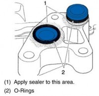
5. Install new O-rings (2) to the oil cooler 

6. Apply sealant (P/N 97720043) to the oil cooler as shown in Figure 1. Do not apply sealant to the O-ring grooves on the oil cooler.

7. Install the oil cooler to the engine block. Torque five oil cooler assembly bolts to 18 ft.-lbs.

8. Allow the vehicle to sit for eight hours at room temperature to allow the sealant to fully cure before initial startup.

Categories
Uncategorized

File-to-Fit Ring End-Gap

The minimum end-gap needed to prevent the top ring ends from butting together under the most extreme operating conditions would be considered ideal. Unfortunately, it is much easier to see and know when you have too little end gap than it is to know exactly what is correct end gap.

Common signs of butting end gaps are: scuffed ring faces, damaged rings and cylinders, and/or shiny areas on the butt ends of the ring. Using recommendations from ring manufacturers, engine manufacturers and your own personal experience is how most engine builders arrive at the desired end-gap.

Current thinking regarding the end gap on most performance engines is to provide a larger gap on the second ring for best performance. Testing has shown a larger second ring gap tends to increase top ring stability allowing for a better seal. This larger “escape” path prevents inter-ring pressure from building up and lifting the top ring off the pistons allowing combustion pressure to get by.

Since the primary function of the second ring is oil control, you can open the gap with no adverse effect on the compression sealing of the ring pack. (There are some applications that don’t benefit from this theory because cylinder pressures are extremely high and the second ring is utilized primarily as a compression ring and not a device for oil control; these would be limited to supercharged/turbo applications.) Many engine builders have reported lower blow-by readings and horsepower gains in the upper RPM ranges with wider second ring gaps.

Steel Alloy Rings
Steel compression rings have many advantages over ductile and cast iron rings such as: higher tensile strength, better yield strength, extended fatigue resistance, greater hardness, lower ring mass, and better cylinder wall conformability. Unfortunately a ring 35% stronger is more difficult to file the end gap compared to the ductile and cast iron rings they replace.

For example, a 4.000” bore would be gapped at .012” out of the package. This allows the ring to fit the cylinder for measurement, right from the manufacturer. This will also allow the occasional customer desiring to run the absolute minimum end-gap to do it with not additional work. This provides the majority of steel performance ring customers to increase the end-gap to their desired specification with less work and time invested in filing of the ring.

Guidelines for Changing Ring End-Gap
Ring end-gap is best measured by inserting one compression ring at a time into the cylinder. Use a ring squaring tool to get the ring sitting squarely about 1” down into the cylinder bore. Using a feeler gauge, adjust the gauge thickness until you have just slight drag as it is inserted into the gap.

If you desire more end-gap, remove the ring and, using a specially designed ring gapping tool, make a square cut on one end of the ring to increase the gap. Using a fine stone, gently deburr the edges of the cut before installing the ring back into the bore for measuring. Improper gapping techniques and improper deburring have ruined many compression rings, so use caution in this process!

Cleaning the Rings and the Block
The process of filing ring end-gaps is a dirty one. Abrasive dust and metal shavings can contaminate your engine. Clean both the rings and the block prior to assembly.

Categories
Uncategorized

Cylinder Head Replacement Tips

Before installing the cylinder head, use an aerosol gasket ­remover to soften traces of baked-on cylinder head gasket. A scraper using a straight razor blade can be especially effective at cutting away gasket residue without damaging the engine block or head. Next, make sure that the blind bolt holes in the cylinder block are clean and free of solid or liquid debris. In some cases, a thread chaser might be needed to clean corroded threads.

After cleaning, a machinist’s straight edge should be used to measure warping in the cylinder head and engine block. If warping exceeds the manufacturer’s specifications, the head needs to be ­repaired or replaced.

Before final assembly, an aerosol parts cleaner should also be used to remove any traces of dirt or liquid contamination from the block and head surfaces. Keep in mind that most modern cylinder head gaskets should be installed dry, without additional sealants. A pair of guide pins can be fabricated to guide the cylinder head into place to prevent damaging the cylinder head gasket. These pins should be slotted at the top for easy removal with a screwdriver. Because over-torquing can ruin modern intake manifolds, follow correct bolt torque sequencing and values when assembling the manifold, plenum and related parts.

Categories
Uncategorized

Caution When Press Fitting Aluminum Timing Gears

When heating aluminum timing gears prior to press fitting on camshafts, caution should be exercised that the gears are not heated above 200 degrees F.

When timing gears are subjected to extreme temperatures, the aluminum gears do not return to their original dimensions after cooling. The result is a loose fit between the gears and camshaft. Under no circumstances should aluminum gears be heated with a torch.

Categories
Uncategorized

Caterpillar Piston Manufacturers’ Casting Numbers vs. Part Numbers

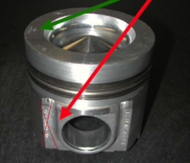
Casting numbers in the skirt or body of the piston may not represent the actual part number of which the casting has been machined.

Depending on the manufacturer, one piston casting could be used for more than one final part number.

Example: 1073565 casting being machined into a 1073565 (piston with one valve relief) or into a 1654262 (piston with two valve reliefs)

Examples of another manufacturer’s casting numbers recorded that are also active part numbers are:

• 7E7600 (3400 series)

• 1073565 (3300 series)

Piston part numbers MUST be taken from the crown of the piston where the part number is usually stamped, etched or inked and NOT from the skirt or bottom of the piston body where it may be cast in.