Categories
Uncategorized

Performance Pistons

This month we’re going to take a look at the various technical aspects of pistons designed for performance and competition engines. If we consider the extreme environment of combustion pressures and high temperatures that regular cast replacement pistons operate in, it’s quickly apparent that when these values are increased it necessitates using a much more efficient component able to withstand these elevated levels. Add to that the much higher and/or sustained RPMs of the engine that could quickly devastate a normal cast part, and selection guidelines become critical.
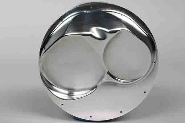
Vertical gas ports, like their horizontal counterparts, are designed to apply pressure to the back side of the top ring to increase sealing load. Which to use when is a question you should ask of your piston supplier.

Manufacturing

There are two types of pistons, cast and forged, and they are manufactured using pretty much the same method as crankshafts except we’re dealing with aluminum instead of steel.


In a cast piece, melted aluminum alloy is poured into a mold which, when cooled, produces a piston that closely resembles its final shape. Casting requires less machining and can be more cost efficient.

The forging process involves placing a heated billet of aluminum alloy into dies. Extremely high pressures compress it into the rough shape of the piston blank. This process requires more machining operations to produce a finished part, which therefore add to the cost. As with a crankshaft though, the forging process gives us a part that is much denser with greater ductility than a cast piece.

All cast pistons contain a certain amount of silicon, generally 10-12 percent, the amount of which is known as the “eutectic point.” Changes to the aluminum alloy can, however, produce stronger cast parts better able to withstand higher output demands. These, known as hypereutectic pistons, have additional silicon added to the alloy that raises it to a 16-18 percent level in the mixture. The piston is still made by the casting process but by increasing the silicon content it gives us a stronger part which also has better thermal efficiencies to handle higher power levels. Hypereutectics can be very cost effective and may be utilized in many applications but they still have limits as to how far they can be pushed and this is where a forged piston becomes a requirement.

Forged pistons are manufactured in two basic alloy configurations, 4032 and 2618. Similar to cast pistons, 4032 forgings generally contain 10-12 percent silicon and are very efficient in numerous applications even when using nitrous oxide or forced induction at moderate levels. The silicon content aids in providing a lower expansion rate of the material as compared to 2618 alloy and can be run with tighter piston to cylinder wall clearances for increasing the lifespan of the engine and also produces less operating noise while the engine is reaching operating temperature.

When it comes to tensile strength between the two, the gap isn’t as large as some might suspect. 4032 has a rating of about 54-55,000 psi, with 2618 coming in at 64-65,000 psi. A 4032 piston is slightly lighter than the 2618 equivalent.
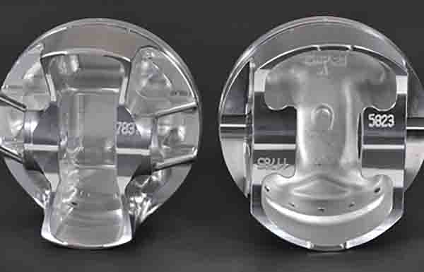
Various designs are used by manufacturers to increase strength while simultaneously reducing weight from the piston. Slipper skirt, full round and side relief designs are the most predominant types.

For high-powered street, maximum competition, high boost forced induction, large doses of nitrous or just about any other build where the pistons have to be as strong as possible, 2618 is the material of choice….or to put it another way, when you’re absolutely, positively intent on squeezing every single drop of horsepower out of your engine no matter how hard you have to push it, use the 2618 material.


This material contains very small amounts of silicon content, usually only 1 percent or less, which produces very high malleability and their strength and thermal characteristics give them the ability to operate in the most extreme conditions. They have a greater expansion rate than 4032 and should be set up with additional clearance to accommodate the growth factor of the piston as it reaches operating temperatures. Because of this they produce more noise than the 4032 when the engine is warming up but their ability to withstand high temps and pressures automatically puts them on the build list for all out power.

One more style of forged pistons is billets.  Billets are made from the same 4032 or 2618 alloy but instead of being produced in forging dies they are machined from solid bar stock. This gives manufacturers the ability to produce a unconventional forging that may fall outside of the predetermined values from forged blanks. They are also great for producing prototypes for testing purposes before committing to an actual piston design.

In addition, a set of billet pistons can provide huge benefits in antique and vintage engines where a replacement piston may be completely unavailable otherwise.  Whichever type you use, the higher strength characteristics and greater ductility will always make a forged piston the best choice for any application that demands maximum horsepower.

Piston Design

Various designs are used by manufacturers to increase strength while simultaneously reducing weight from the piston. Slipper skirt, full round and side relief designs are the most predominant types used in current piston technology.
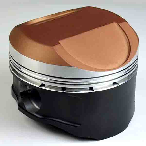
This Hemi piston has both anti-friction and ceramic coatings applied.

Slipper skirt designs are intended to decrease the amount of contact area compared to a more traditional full round design and only employ skirt area on the thrust sides to provide operational stability. The side reliefs are forged in place, which also removes considerable weight from the piston and allows it to function well at higher engine speeds.

Another variation of this style sees the pin boss moved further inward to use a shorter wrist pin and provide more clearance while again providing additional weight savings. Strengthening ribs can also be designed into the piston to reinforce the pin boss area. Another variation is the use of asymmetrical skirts, which provide a greater surface area on the major thrust face of the cylinder and reduced on the minor thrust area.

Full round designs provide the largest amount of skirt area but can have side reliefs machined in place for many applications. This design can be utilized in applications that will see very high pressures because of the amount of contact area. The lower band below the pin area can be left for stability purposes or machined away for additional counterweight clearance on large stroke engines.

If you aren’t quite sure about the best piston design to use for your build (or specific features) call the manufacturer of your choice and they can quickly provide the info you need to make the power you want and give the highest amount of service life for your engine.

Coatings

Piston coatings can be used to achieve a number of operational benefits and are composed of various compounds and processes from graphite to ceramics to anodizing, etc. Many piston manufacturers and coating companies have their own particular names for the coatings they offer but in order to simplify our discussion we will generally cover the chemical compositions and areas of the piston on which they are used.
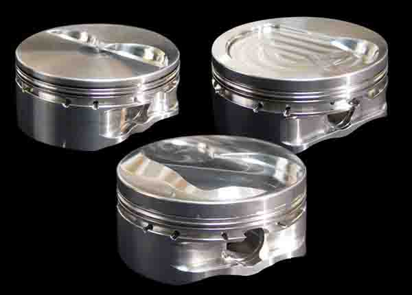
If you aren’t quite sure about the best piston design to use for your build (or specific features) call the manufacturer of your choice and they can quickly provide the info you need to make the power you want.

• Ceramic coatings are used on the piston crown in order to reflect heat into the combustion chamber and away from the top of the piston. In certain builds, Ceramics can be utilized in the combustion chamber and on the valve faces to better control the thermodynamic characteristics of the engine and lower overall cylinder head temps.

• Moly dry film coatings are applied to the skirts to reduce friction and help prevent premature skirt wear.

• Oil shedding compounds are applied to the underside to help reduce the amount of oil that is clinging to the piston and adding weight. These type of coatings can also be applied to the crankshaft and connecting rods in order to achieve the same purpose.

• Anodized coatings can be employed for multiple applications. When applied to ring land areas anodizing can provide wear resistance and help prevent the piston rings from micro-welding to the ring grooves. Another form of hard anodizing is used to coat all the surfaces of pistons used for Top Fuel engines. This coating can withstand the higher temperatures and also helps combat the corrosive characteristics of nitromethane. Hard anodizing is also used on pistons for high boost and nitrous engines because it can handle the elevated temps and pressures of these builds.

Piston Pins

Pins do more than just connect the piston to the rod – they play a big part in making consistent power and helping to keep the engine alive. Failures blamed on the piston can often actually be traced to using the incorrect piston pin for the application. Viewing it strictly from a financial standpoint, upgrading pins can be a substantial increase to the overall cost of a set of pistons. If we continue to follow that train of thought however, it will eventually lead to the realization that a failure in this area can cause tremendous amounts of financial woes due to associated damage to other components in an expensive engine.

For most naturally aspirated street engines and certain competition applications like late-model stock circle track for example, the standard case hardened carbon steel pins will work fine in the 600-650hp range. But pin requirements could change for this level of power output when using nitrous oxide or a blower. It doesn’t necessarily mean that the pin material itself must be upgraded – sometimes utilizing a thicker wall pin of the same material can compensate for the extra pressures placed on the engine. My main focus here is to get you to think of the wrist pin as more than just an attachment device.

High horsepower NA builds or engines that have big boost numbers being pushed through them must use pins that can endure the pressure and RPMs. In other applications though, a pin upgrade can enhance performance and provide additional insurance against failures.
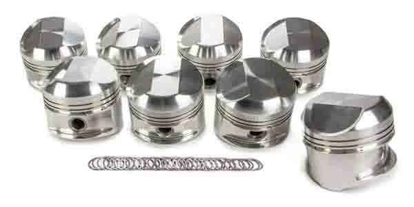
There are numerous design features that can be added to most forged pistons that will give you a longer service life in a performance or competition build and also help deter operational issues that could arise.

There are some combinations that we use for certain circle track engines that are well below the horsepower levels that would dictate a heavy duty upgrade but by using DLC coated pins we substantially reduce friction and have no concerns about them lasting for an entire season of racing. 

When choosing the pistons for your next build take the time to evaluate the possibilities of benefits that can be derived from matching the wrist pins to the exact application that the engine will be used for.

Piston Features

There are numerous design features that can be added to most forged pistons that will give you a longer service life in a performance or competition build and also help deter operational issues that could arise. Things like contact reduction grooves, dual pin oilers, lateral and vertical gas ports, accumulator grooves and internal milling just to name a few. All of these are listed on the piston manufacturer’s websites with complete descriptions of the purpose for each feature.  There have also been changes made to the axial and radial dimensions of piston rings that are being used in performance applications to achieve more power and better sealing qualities. Choosing the right piston and pin configuration will reward you with the confidence that the cylinders are filled with exactly what your engine and customer needs.
Categories
Uncategorized

Carbon Deposit Buildup in Diesel Engines and How to Prevent It

Carbon deposit buildup on diesel engine components such as piston heads, fuel injectors and intake valves is a bigger problem than it is for gasoline engines. There is a federal requirement that certain detergents be added to gasoline at the refinery itself, but there is no such mandate for adding detergents to diesel fuel. For this and many other reasons, diesel engines are more susceptible to carbon deposit buildup.

Most of the blame, however, has been assigned to the fact that the fuel spray from a diesel injector goes directly into the cylinder bypassing, for example, the back of the intake valve where deposits are likely to form. The increasing use of high pressure common rail fuel systems have also increased engine deposits. Other reasons for diesel engine carbon deposits are the use of low-quality fuel, short cold weather trips, excessive idling, infrequent oil changes and even dirty air filters.

“In addition to adopting good driving practices, the best thing you can do to keep a diesel vehicle in optimal driving condition is to keep the engine clean of carbon deposits,” says Christopher Miller, vice president, E-ZOIL. The company manufactures fuel additives and cleaning solutions for fleet owners and consumers to protect their diesel vehicles and equipment.

Once carbon buildup begins to accumulate on various surfaces inside the engine and is left untreated, the vehicle loses power, becomes sluggish and causes a significant increase in emissions and reduction in fuel economy. No doubt all of this erodes the mileage and performance gains expected of a diesel engine and if we are talking about a fleet of 1,000 vehicles or more, it ultimately hurts the owner’s profit margin.


Miller recommends that diesel vehicle owners use a fuel treatment especially formulated for high pressure common rail fuel systems. For example, E-ZOIL’s diesel fuel system cleaner, Carbon Crusher, incorporates state of the art detergents that can clean the entire fuel system. These detergents help fight both traditional coke deposits and internal diesel injector deposits (IDID) and dissolve asphaltenes, which clog fuel filters. Carbon Crusher also includes a heavy-duty lubricant and cetane, which enables diesel fuel to ignite faster and help the engine run more smoothly and efficiently.

“Using a quality diesel fuel system cleaner to keep the engine clean will ensure that the vehicle will continue to give you the power and performance for which it was built in the first place,” said Miller.

Categories
Uncategorized

Break-In Oils and Assembly Lubes

Perhaps the most important property of lube oil is its ability to remove heat from a surface where two or more metals are sliding across each other. In much the same way as air flows around cylinder head fins to remove heat, oil flows through a bearing and removes the heat caused by friction. I can’t imagine the destruction which would follow from assembling an engine completely dry.

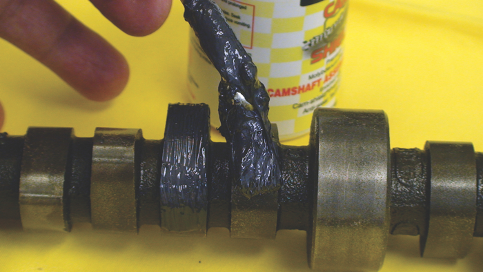
A thin coating of assembly lube should be applied on all high-friction, high-load surfaces including rod, main and cam bearings.

A thin coating of assembly lube should be applied on all high-friction, high-load surfaces including rod, main and cam bearings.

Assembly Lubes

Assembly lubes are one of the most important parts of an engine build. But, some components are hard to lubricate prior to start-up, and other parts allow assembly oils to drain off during storage. Let’s address the best way to overcome both of these problems.

Prior to learning about greases, I used a mixture of SAE 30 grade motor oil and STP on my engine builds. I put that very stiff goo on everything from rod and main bearings to pushrod tips. The engines I built using this technique were often very hard to turn over fast enough to start in the days before gear-reduction starters.

Then I learned to use my head for something other than a hat rack. Most engine builders (other than the fueler gang) pre-lube their engines by either pressurizing the oil galleys or spinning the oil pump until sufficient oil pressure is achieved. This means builders can use oils similar in viscosity to the oils they would actually operate their engines on. Hard engine turnover problem solved.

But what about those engine components not directly lubricated by engine oil pressure? Camshaft lobes, flat tappet lifters, and pushrod tips are lubricated only by splash after the engine is running. One can use oil to lubricate these parts prior to startup, but what about long-term storage?

Long-term storage can allow oil to run off these parts over time. But if we think about it, grease is merely a mixture of oil with what chemists would refer to as a soap substrate. Grease is designed to hold the oil in suspension until sufficient heat or motion builds up to release the oil and allow it to do its job. Grease is the perfect solution to stop run off.

From that day forward I’ve used high performance engine oil to lubricate all engine components except flat tappets, cam lobes and valve train components when assembling an engine. I even use oil on the cam bearings and journals, but on the cam lobes, flat tappet lifters and pushrod tips I use grease. You don’t have to use grease on cam lobes and roller lifters, because roller lifters don’t slide across the cam lobe. I’ve had zero failures since I learned to use grease.

Fueler racers use very heavy oil (60 or 70 grade), grease, or a newly developed gel on their engine components, because they just don’t have sufficient time between engine rebuilds in the pits. Besides, those hand-held starters deliver a lot more torque than smaller, gear-reduction starters.

However, I’ve learned something very important about which properties you must have in the grease you utilize.  First, the grease must be oil soluble.  If you use a grease like a white paste many people used years ago, you will find this material is not oil soluble, and you will plug oil filters with a white residue. That’s okay if you remember to change oil filters immediately after the engine is run for a few minutes, but I like things to be automatic so I don’t have to rely on my faulty memory.

Secondly, it’s a good idea to use extreme pressure (EP) grease, particularly when you have high lift cams and very stiff valve springs. Some greases just don’t have the film strength to protect components where the contact area is limited (like pushrod or valve tips). Even lifter contact takes place over an area much smaller than you would think. So I prefer to use EP grease all the time; it’s just cheap insurance.

Another area which needs to be addressed is the use of lubricants to properly torque head and rod bolts. Since this is a very involved discussion, I’ll save it for a subsequent article. There are some very important things to consider about torqueing bolts.

Some assembly lubes have a paste-like consistency and are applied with a brush while others are more like honey and can be applied from a squirt bottle.

Some assembly lubes have a paste-like consistency and are applied with a brush while others are more like honey and can be applied from a squirt bottle.

Break – In Oils

I recall building an engine with chrome rings back in the ‘60s. I couldn’t get a decent break-in in spite of everything I did. I couldn’t figure it out, so I quit using chrome rings.

Then in the early ‘80s Daimler-Benz was using a very high-quality, high-TBN diesel engine oil as factory fill in all their engines to enable oil change intervals as high as 100,000 kilometers. They contacted us because these engines were burning excessive oil for many thousands of miles, and many customers were demanding expensive rebuilds prior to the warranty period expiring.

After considerable engine and field testing we discovered the high TBN diesel oil was preventing sufficient cylinder liner and piston ring wear to break the cylinders in. The harder piston rings, combined with the centrifugally cast alloyed cylinder liners and the excellent diesel oil had reduced wear to the point that some of these engines took over 50,000 miles to fully break in.

This is unacceptable, so we investigated the problem. We found that most wear in the piston ring/cylinder wall regime was caused by chemical corrosion, not lack of EP protection. But good EP protection was still necessary to prevent valve train failures during the break-in period. We then formulated a Daimler-Benz first-fill break-in oil, which had lower levels of detergency yet adequate ZDDP levels to protect valve train components. Problem solved.

Years later, I was talking with the head engine builder at Richard Childress Racing, and he stated that good, quick cylinder sealing was very important to his NASCAR engines. We drew upon our Daimler-Benz experience to formulate a low detergent, high ZDDP break-in oil for him to evaluate. Since automotive engine oils often contain friction modifiers, we also looked at the effect on break-in rate. Our resultant recommendation contained increased ZDDP, low levels of detergent, and no friction modifiers.  The results were impressive, and he was very happy.

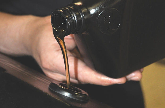
oil_pour

So what did we learn? It is imperative that the piston rings and cylinder walls quickly wear to the point that cylinder pressure leakage is minimal. Break-in oils can speed this process significantly over fully formulated automotive or racing engine oils.

This concept has been both dyno and field tested many times, and results have always been better than when using typical engine oils.

Conclusion

I keep a large container of break-in oil and a smaller container of EP grease in my shop at all times. Even though I once fired up an engine without an oil pump pressure relief valve installed, I’ve never suffered a failure due to lack of lubrication. The mixture of assembly lube and grease has always protected valuable engine components until the engine could be safely broken in.

Categories
Uncategorized

Selective Catalytic Reduction?

The Diesel Technology Forum recently issued the following explanation on Selective Catalytic Reduction (SCR), an advanced active emissions control technology system used in clean diesel engines.

Selective Catalytic Reduction (SCR) is a proven and advanced active emissions control technology system that injects a liquid-reductant agent through a special catalyst into the exhaust stream of a diesel engine. The reductant source is usually automotive-grade urea, otherwise known as Diesel Exhaust Fluid (DEF). The DEF sets off a chemical reaction that converts nitrogen oxides into nitrogen, water and tiny amounts of carbon dioxide (CO2), natural components of the air we breathe, which is then expelled through the vehicle tailpipe.

SCR technology is designed to permit nitrogen oxide (NOx) reduction reactions to take place in an oxidizing atmosphere. It is called “selective” because it reduces levels of NOx using ammonia as a reductant within a catalyst system. The chemical reaction is known as “reduction” where the DEF is the reducing agent that reacts with NOx to convert the pollutants into nitrogen, water and tiny amounts of CO2. The DEF can be rapidly broken down to produce the oxidizing ammonia in the exhaust stream. SCR technology alone can achieve NOx reductions up to 90 percent.

SCR System

Why is SCR important?

SCR technology is one of the most cost-effective and fuel-efficient technologies available to help reduce diesel engine emissions. Its effectiveness allows diesel engines to be tuned and optimized toward maximum fuel efficiency, while the SCR systems are highly efficient at treating the engine-out exhaust.

The largest sector for use of SCR technology in the US is heavy-duty commercial trucks.  All heavy-duty diesel truck engines produced after January 1, 2010 must meet the latest EPA emissions standards, among the most stringent in the world, reducing particulate matter (PM) and nitrogen oxides (NOx) to near zero levels. SCR can reduce NOx emissions up to 90 percent while simultaneously reducing HC and CO emissions by 50-90 percent, and PM emissions by 30-50 percent.

In the commercial trucking industry, some SCR-equipped truck operators are reporting fuel economy gains of 3-5 percent. Additionally, off-road equipment, including construction and agricultural equipment, must meet EPA’s Tier 4 emissions standards requiring similar reductions in NOx, PM and other pollutants.  SCR is also used in some of the many different applications of off-road engines and equipment.

Where is SCR used?

SCR has been used for decades to reduce stationary source emissions from various industrial operations. In addition, marine vessels worldwide have been equipped with SCR technology, including cargo vessels, ferries and tugboats. With its superior return in both economic and environmental benefits, SCR is also being recognized as the emissions control technology particularly helpful in meeting the U.S. EPA 2010 diesel engine emission standards for heavy-duty vehicles and the Tier 4 emissions standard for engines found in off-road equipment. SCR systems are also found in the growing number of diesel passenger vehicles.

What are the special considerations of using SCR?

One unique aspect of a vehicle or machine with an SCR system is the need for replenishing Diesel Exhaust Fluid (DEF) on a periodic basis. DEF is carried in an onboard tank which must be periodically replenished by the operator.  DEF consumption rates are determined by vehicle operation.  More aggressive driving at higher speeds or while hauling heavy loads will increase DEF consumption.  For most light-duty vehicles, DEF refill intervals typically occur around the time of a recommended oil change or other scheduled vehicle maintenance.  DEF replenishment for heavy-duty vehicles and off-road machines and equipment will vary depending on the operating conditions, hours used, miles traveled, load factors and other considerations.

DEF is an integral part of the emissions control system and must be present in the tank at all times to assure continued operation of the vehicle or equipment. Low DEF supply triggers a series of escalating visual and audible indicators to the driver or operator. Once the tank reaches a certain level near empty, the vehicle starting system may be locked out the next time the vehicle is used, preventing the vehicle from being started without adequate DEF.

On-board tanks to store DEF are typically located in the spare tire area of passenger vehicles, while tractor trailers typically have a DEF tank alongside the diesel fuel saddle tank. Proper storage of DEF is required to prevent the liquid from freezing at temperatures below 12 degrees Fahrenheit, and most vehicle DEF dispensing systems have warming devices.

What is DEF?

Diesel Exhaust Fluid (DEF) is a non-toxic fluid composed of purified water and automotive grade aqueous urea. DEF is available with a variety of storage and dispensing methods. Storage options consist of various size containers such as bulk, totes and bottles or jugs. The American Petroleum Institute rigorously tests DEF to ensure that it meets industry-wide quality standards.

A nationwide DEF distribution infrastructure has rapidly expanded to meet the needs of a growing SCR technology marketplace.  Since 2010, DEF has been widely available for purchasing at various locations like service stations, convenience stores, automotive parts stores, Wal-Mart, and petroleum retailers as well as truck stops, truck dealerships and engine distributors.  DEF tanks on vehicles typically range in size from 6 to 23 gallons depending on the type of vehicle application. The DEF tank fill opening is designed to accommodate a DEF fill nozzle to ensure only DEF is put into the tank. A diesel fuel nozzle will not fit into the DEF tank opening.

Most heavy-duty truck manufacturers calculated operating costs of new SCR-equipped vehicles based on a DEF price of $3 per gallon, however, the price of DEF responds to market conditions of supply and demand and is expected to decrease due to the growing network of DEF supply.

Categories
Uncategorized

Complexities of Modern Timing

Let’s face it: timing used to be relatively easy. These days, however, as with most every other engine component, the technology and innovation that leads to more fuel efficiency and performance also means increased complexity with timing components.

You’re already facing challenges in understanding late model chain drive timing systems and how to properly set up the camshaft, crankshaft and balance shafts along with the electronic sensors used by the powertrain system (aka, the computer) to achieve correct engine performance – guess what? That’s unlikely to change.

Speaking with leading timing component manufacturers, one thing is clear – timing is critical and will only continue to be more important.

“We’ve seen a shift away from conventional three-piece timing sets,” explains one manufacturer. “As such, the more modern timing setup – with the sprockets regulating the firing of the engine – will continue to become more critical.”

Take the GM V6, 3.6L DOHC engine, for example. Like some bizarre math word problem, this DOHC, four camshaft engine uses two idler sprockets requiring three separate timing chains to operate the timing system. There are four camshaft sensors and a crankshaft sensor used to operate the VVT system, etc. The front of the engine is shown below and includes 15 pieces needed to service this timing system – that doesn’t include any of the VVT components.

“Unlike older engines, late model applications use multiple camshafts and balance shafts requiring more sensor input to the computer to lower emissions while gaining horsepower and torque,” says one timing component manufacturer. “This also controls VVT operation. A check engine light can easily be triggered if new timing components are not properly installed and every engine is a little bit different.”

The overall systems have gotten more complicated,” says one expert. “We’ve successfully made the adjustment from yesterday’s three-piece sets to overhead cams but I think now, we’re still reacting to the many different versions, as well as adding VVT or even twin VVTs per head. That’s extra rotating mass, which is more demanding on the chains themselves.  Variable valve timing loads the system dynamically, which adds loads that change due to the valvetrain changes. The relative motion itself strains the system when the VVT is in operation.

In addition, these systems depend heavily on hydraulics and the hydraulic system to support the stability of the system. This puts more demand on the engine’s hydraulic system and you’re depending on the timing system to keep it all stable.

It’s a vey interdependent system and, explains one of our experts, when this stuff decides to fail, it’s the perfect storm.

We’re seeing much smaller pitch that have less rotating mass which, on some levels, makes total sense. However, smaller components can add challenges on other levels.  Components have gotten smaller and more lightweight so we’re demanding more from less material.

“When you do small pitch systems the sprockets get smaller, your forces go up and the demands on the chain per component go up,” a supplier says.

Trying to keep up in the aftermarket, our experts say, is the tricky part. The game has changed – 30-40 years ago in the golden era of three-piece sets, what the aftermarket produced was better than what the OE could. It wasn’t that difficult to make a better part than OE. The aftermarket could make modifications to improve the part.

Now, the OE has the ability to invest enormous amounts of testing and equipment to develop premium products. “Our challenge is to produce a part in the aftermarket at lower volumes that is price competitive and still meets that quality standards. We have to do it differently, but we’re figuring our way through it. We’re meeting these challenges by being smarter and more involved with component setups.”

One leading supplier says that he anticipates engine builders will rely more heavily on domestic manufacturers that have extensive experience at the OE level and who can provide increased support. Additionally, technical education will be more important in order to repair these engines, and their computer skills in particular will play a larger role in the job.

In general, overhead cam engines will pose greater repair complexity. Certainly newer engine designs such as Ecoboost, Duratec, Hemi and emerging diesel platforms will require specialized knowledge with regard to timing.

“We haven’t met our peak yet with technology – the OEs will continue to come up with innovations,” said one manufacturer referencing replacement components for turbocharged or direct injection applications.

In addition, specific timing chain tensioner designs can present issues.
According to one manufacturer, the timing chain tensioner is the heart of the timing system just as the oil pump is for an engine. Often overlooked, if proper tension isn’t maintained the system will prematurely fail.

Slack in the chain will cause it to ride up on the sprocket teeth and stretch or break the chain. Timing systems using hydraulic chain tensioners are operated by using engine oil and oil pressure.

Variable valve timing is the state of the art, according to industry experts, but even this new technology will be surpassed in the aftermarket. How turbocharging, direct-injection and other future technologies impact ever-smaller timing components will be the next challenge.

One other note for hydraulic tensioners used in the late-model timing systems. Using the correct OE design oil filter with “check valve” along with recommended oil viscosity has become critical on these systems. If there’s a delay in oil pressure on initial startup the system will not have the correct amount of tension on the chain causing it to ride up on the sprocket teeth. The chains have become so long on overhead cam engines that the system will not tolerate slack in the chain(s) for very long without damaging the system.

Installers often don’t realize how these operate and are affected by the overall condition of the engine. It’s critical that the engine is operated using the correct type of oil and oil viscosity.

Oil changes must be done when recommended by the OE manufacturer to keep a clean oil supply. The tensioners have very small oil passages and check valves that can become plugged, reducing the amount of pin pressure being applied to the tensioner arm or chain.

When a timing system fails and it uses hydraulic tensioners, other areas of the engine must be checked before installing new timing components. The overall condition of the engine has to be good. A worn engine will have problems with oil pressure whether cold or hot / idle or while driving and could have sludge and dirt built up inside it. A low oil level can introduce air into the oiling system and cause problems with these tensioners resulting in an intermittent pounding effect on the chain instead of constant steady pressure.

Because clogging of these tensioners and VVT solenoids is such a dangerous threat, some OE manufacturers have started putting internal check valves along with oil screens inside of the tensioners and solenoids to extend life. Others are using what’s called a ratchet design that holds tension on the tensioner pin maintaining tension on the chain when the engine isn’t running.

Engine startup after sitting overnight and cold ambient temperatures can cause a delay in what manufacturers call tensioner “pump up” and can cause a sudden pounding effect on the timing chain causing abnormal wear on the tensioner arms and guides. The arms and guides are normally made of plastic or have a plastic liner for the chain to ride on with an aluminum back/carrier.

The bottom line, experts say, is that you must use the correct type of oil and viscosity. Remind your installer customer to tell their customers that regular oil changes must be done to maintain a clean oil supply.

Engine builders are often made aware of the timing challenges they face after there is a problem. However, industry leaders say professional builders and installers  very quickly learn and adapt to the technology – we’re in an age with easy-to-access technical information – QR codes that will take you to installation instructions or electronic repair manuals – people have learned that it’s much better to go about it informed than try to take a stab at it. It’s too dangerous and expensive to take chances.

Resources like the one you’re holding can help you keep up with the latest developments. Suppliers say specialized knowledge of VVT, cam phasers, solenoids and the interrelationship of each will be key to doing the job right the first time and avoiding an expensive comeback.

Manufacturer catalogs and websites have detailed installation tips and instructions, product photography and technical information.

But it will also be up to you to continue to invest in education on the electronics side. Computer and drivetrain technology will continue to change. Access to OE service information will be a must along with a good understanding of engine design. For example, one manufacturer reminds our readers that you must know the difference between an interference and non-interference engine before you attempt to service the timing components. You’ll also need access to the special tools used to hold the camshafts and crankshaft to avoid rotation and possibly damaging the valve train components and pistons.

Categories
Uncategorized

Building for Biodiesel

Some people have a negative view of biodiesel. They say it gums up the fuel pump and injectors. They say it gels in cold weather. They say it’s diverting food resources to make fuel. They say it’s too expensive and can’t compete economically with conventional No. 2 diesel fuel.

Then they hear that diesel engines burning biodiesel are winning pulling championships, drag races and setting new land speed records. Maybe biodiesel isn’t so bad after all.

There’s a lot of misinformation and disinformation about biodiesel on the Internet. Truth is, it’s actually a good alternative fuel for diesel engines – provided the fuel meets the quality and performance requirements for the application. It can be blended with ordinary diesel fuel or burned straight. Biodiesel is being successfully used in everything from daily drivers to tow trucks to Class 8 semi-trucks, and for performance applications ranging from truck and tractor pullers to drag racers, road racers and even Bonneville speedsters.

There are a number of resources on the web providing detailed technical information about biodiesel. These websites have tons of info about biodiesel fuel characteristics, fuel quality standards, materials compatibility, lubricity benefits, fuel blending, and which automakers approve biodiesel in its vehicles. A list of association sites is included in this article.

The National Biodiesel Board represents the biodiesel industry and obviously promotes biodiesel as an alternative fuel for the benefit of its members. Even so, there are a lot of proponents of biodiesel who have nothing to do with producing, distributing or selling alternative fuels. These range from everyday consumers who drive diesel-power vehicles to professional racers who run 2500-plus horsepower diesel-powered trucks and tractors.

Greg Randall of the National Tractor Pullers Association said his organization began allowing B100 (a 100% straight blend of biodiesel) at its pulling events starting in 2013. The results were immediate. Pullers who were burning B100 were beating everybody else and winning events. Most pullers are secretive about their fuel mixtures because they know the right fuel blend can make more power and give them an edge over their competitors. “We used to test fuel mixtures to check for additives, but this year we are not requiring any fuel tests,” said Randall. The only requirement is that the fuel be some type of diesel derivative (conventional, synthetic or biodiesel) and that it does not contain oxygenators.

Bryce Anderson of the United Pullers of Minnesota says his organization has allowed biodiesel for the past couple of years. “We have seen no mechanical issues with fuel pumps or injectors.” But he did caution that straight B100 can damage rubber hoses so it’s important to use neoprene or silicon hoses and o-rings that are biodiesel compatible in the fuel system.” Other than that, no engine modifications are needed to burn biodiesel.

Anderson says B100 can make 6 to 10 percent more power than conventional diesel fuel, which translates into 100 to 200 more horsepower depending on the power level of the engine. He said B100 is winning national titles and setting world records because it is a better racing fuel than ordinary diesel. Competitors are using biodiesel in tractors, trucks and even semi-trucks at most events. And many of the spectators who attend these events are also using it on a daily basis in their own vehicles (typically B5 or B10 blend).

Anderson says that once somebody wins an event on B100, everybody else wants the same advantage. Those who aren’t taking advantage of what B100 has to offer are finding it harder and harder to remain competitive.

Back in 2011, a Hajek Motorsports Ford F-250 pickup truck powered by a 6.7L Powerstroke engine burning B20 biodiesel set a land speed record of 182 mph at Bonneville. This smashed the previous record of 167 mph, which had been held by a GMC Duramax.

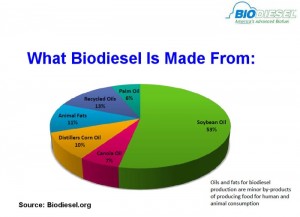
biodiesel_pie_chartWhat Is Biodiesel?

Biodiesel can be made from a variety of plant oils including soybeans and corn oil. About half of the biodiesel that’s sold in the U.S is made from soybeans. It can also be made from recycled cooking oils or animal fats, including byproducts from chicken, pork and beef processing plants that would otherwise go to waste. It can even be made from algae. Running a diesel engine on soybean oil, recycled deep fat fryer grease or refined chicken guts may seem risky, but as long as the fuel meets quality standards, it’s safe to use. And in higher concentrations, it can provide a significant power gain.

Biodiesel usually requires no internal engine modifications or changes to the fuel delivery system. The engine’s compression ratio does not have to be changed. If an engine is running B100, it can usually handle some additional compression to maximize the cetane rating of the fuel (which can vary depending on what the fuel is made from). Biodiesel made from vegetable oils typically has a cetane rating of 46 to 52, while biodiesel made from animal fats has a higher rating of 56 to 60.

Low blends such as B5, B10 and even B20 burn pretty much the same as ordinary No. 2 diesel oil. However, straight B100 tends to be dirty at idle (produces more black smoke) – which usually doesn’t matter at a pulling event or drag race because fans like to see lots of black smoke.

The American Society of Testing Materials (ASTM) has quality standards for different blends of biodiesel, including ASTM D6751-12 for B100, ASTM D7467-13 for B6 to B20 blends, and ASTM D975 for B5 blends. According to ASTM, low-level blends such as B5 are approved for use in any compression-ignition diesel engine, including cars, light or heavy-duty trucks, marine or stationary engines.

B5 is commonly available in many areas of the country and is OEM approved for use in many diesel-powered vehicles. B20 is also a popular blend (20% biodiesel) and is used in many fleet applications. B20 may also be OEM approved for certain vehicles. Performance and fuel economy on B5 to B20 blends is similar to that on straight No. 2 diesel fuel. B100 actually contains less energy per gallon than ordinary diesel, but its higher cetane rating allows it to produce more power under high boost pressures.

American automakers typically require a minimum cetane rating of 40 for most engines, but European automakers typically specify a minimum cetane rating of 51.

A bit of history trivia worth mentioning here is that the very first diesel engine invented by Rudolph Diesel in 1893 ran on vegetable oil. So the case for biodiesel goes a long way back.

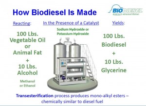
how_biodiesel_is_madeWhy Biodiesel?

Biodiesel was originally promoted as a homegrown renewable alternative to expensive oil imported from offshore producers. Depending on crop prices and world oil prices, biodiesel can compete economically with conventional diesel fuel. It also burns cleaner than diesel fuel, reducing greenhouse gas emissions. And as truck and tractor pullers have discovered, it can also make more power and win events.

Today, however, the economics is more challenging. In recent months, Saudi Arabia has been flooding the world market with crude oil to drive down oil prices. Oil that used to sell for over $100 a barrel has been selling as low as $48 a barrel, and is currently bouncing around $54 to $58 a barrel. Although low oil prices mean less cash flow into Saudi coffers (which are already stuffed with mega billions of dollars), it also means U.S. shale oil producers and biodiesel producers are finding it harder to compete with cheap Saudi oil. Crude oil prices generally have to be above $60 a barrel for many alternative fuel sources to remain profitable.

Currently, the U.S biodiesel industry has the capacity to produce almost 2 billion gallons of biodiesel a year. However, the U.S. Energy Information Administration reported that in 2014, only 1.27 billion gallons of biodiesel were produced, which was down from a peak of 1.36 billion gallons in 2013 – which means there is a lot of excess capacity in the biodiesel industry that is not being used.

The Federal Renewable Fuel Standard (RFS), which came about as part of the Energy Policy Act of 2005, requires oil companies to blend a certain amount of biodiesel and ethanol into diesel and gasoline for the purpose of extending domestic fuel supplies, reducing our dependence on foreign oil and for reducing emissions. Big Oil hates the RFS requirements because it cuts into its profits, and it’s been fighting hard to kill it. In the meantime, the Feds have been dragging their feet on setting the amount of biofuel that’s required for 2014 (which is already past history) and for 2015 and beyond. The biodiesel producers are hoping the numbers will increase so they can utilize more capacity, while Big Oil is pushing for smaller numbers or to eliminate the requirements altogether.

So how does all of this affect engine builders? Building performance diesel engines is pretty much a niche rather than a broad market opportunity. Although the basics of building a performance engine to run on gasoline is similar to that of building a performance engine to run on diesel, there are a lot of differences that require experience and know-how to compete successfully in highly competitive events.

Biodiesel is just part of the equation to making as much power as possible in both stock and highly modified engines. The bottom line is if you can build a competitive engine that runs on conventional diesel fuel, you can also build an even more competitive engine that will run on B100 biodiesel.

Another article in this issue discusses the upgrades in the crankshaft, connecting rods and pistons that are usually necessary when producing big horsepower numbers. So whether the fuel is conventional diesel or biodiesel, the basics inside the engine remain the same.

Categories
Uncategorized

ENGINE BEARINGS FUNDAMENTALS: Lugs or no Lugs

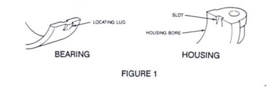
We left off talking about bearing and bushing retention and the terms “Crush” and “Press Fit”. The locating lug on a half shell bearing registers with a mating slot in the housing to locate the bearing shell (figure 1). The lug is not intended to prevent bearing rotation. Crush holds the bearings in place and prevents spinning just as press fit holds bushings in place which have no locating lugs. Each ½ shell bearing has about .004” or so of crush. That is to say: each shell is slightly bigger than ½ circle. When the two halves are assembled and caps tightened to spec, the extra material (crush) creates radial force against the housing bore, holding the bearings in place and insuring good heat transfer.Lugs


Lugs can be positioned differently on upper and lower halves or varied in width to prevent misassembly. A number of late-model engines have even eliminated the location lug completely. Regardless of lug or no lug, proper positioning of a crankshaft bearing is essential to ensure oil hole alignment with the housing and to prevent interference between the edge of the bearing and the crankshaft fillet radius.

Some confusion has arisen over the “Lug-No Lug” bearing issue. For engines like the 6.7L Ford diesel, it is quite simple. Every 6.7L diesel engine ever built by Ford has both main and rod bearings with no locating lug so supplying an aftermarket set from Clevite is very simple: no lugs! Where it becomes confusing is an engine family like the 4.7L Chrysler V-8. Chrysler made a production change during the life of the 4.7L going from a lugged design on the bearings to a non-lugged design. Clevite, as did most bearing suppliers, elected to supersede the lugged design to the non-lugged design. The non-lugged part will work in the earlier designs but of course the reverse is not true.

Positioning the non-lugged bearings requires a bit of care so the edge of the bearing shell does not interfere with the radii on the crank. Once you have the shell positioned, free-spread provides the good fit that holds the bearing in that position while you assemble the engine.

Finally, just in case you are wondering about the removal of location lugs by engine manufacturers, it is simple economics. Take a popular example like the 6.7L Ford. The engine has 5 main bearings and 8 conrod bearings. Eliminating the lug pockets in the block and main caps reduces by 10, the machining cuts made at the factory. Add another 16 cuts eliminated on the conrods and you can see, just the savings in tool bits would be substantial, not to mention operator time and machine time savings as well.

Categories
Uncategorized

Water Injection Systems Coming Back

The idea of injecting water into the combustion chamber of an engine has been around since the 1940s when it was first employed in aircraft engines. While weaving in and out of cars since the 1960s, the technology has never really caught on. However, BMW recently announced that they would be marketing their upcoming M4 GTS, due to arrive this summer, with a water injection system. This development now presents the question of whether or not the technology will finally become widespread in the performance segment.

Also known as anti-detonant injection, this technology first appeared in 1962 on the Oldsmobile 215 Turbo Jetfire engine. The Turbo Jetfire was an early turbocharged design that sprayed distilled water and methanol into the combustion chamber. Chrysler also experimented with the technology in the early 1960s, and the Saab 99 Turbo offered water injection during the 1970s. Water injection was consequential on early turbocharged cars, used to keep combustion chamber temperatures lower. However, once the development of the modern day intercooler accelerated, water injection systems seemingly went on the wane.

In today’s day and age, despite the claims that water injection systems are rendered unnecessary on forced induction engines, the technology still introduces a cadre of fundamental benefits, perhaps the reason why BMW is investing in it.

The benefits of a water injection system stem from the ability of water to absorb heat in the combustion chamber and reduce temperatures. This has the obvious effect of reducing pre-ignition and detonation of fuel and thereby preventing knocking. In modern day applications, this may be used to support a higher compression ratio, for more power and greater efficiency- an adjustment usually not allowed due to the threat of detonation.

Higher levels of boost can also be reaped from forced induction engines due to the reduced probably of detonation after water injection; water cooling of the ambient intake air may allow for greater density and therefore more air content to be packed into the cylinder.

Water injection can also be used to reduce the overall thermal load on a high-performing engine by cooling engine components normally exposed to massive amounts of heat, in addition to ambient air inside the combustion chamber. Exhaust gas temperatures have also been consistently shown to be lower on water injection engines, due to lower initial intake and combustion temperatures. However, exhaust gas temperatures do increase noticeably as more methanol, which is commonly coupled with water in such systems, is added.

Common in aftermarket settings, the technology is used on high performing engines, and several companies offer water injection systems for aftermarket sale. Many use these systems to reduce the need for an intercooler or to be able to run smaller intercoolers on their engines, in the interest of lessening pressure drop through the intercooler system and eliminating resultant turbo lag; though it currently remains a subject of debate as to whether or not this is the best course of action.

Methanol injection is also commonly used in conjunction with water injection. In fact, most of the aforementioned systems being marketed today are 50/50 water-methanol injection systems. The presence of methanol effectively increases the octane rating of the delivered fuel/air mixture, affording better protection against detonation and more power. Oils have also been delivered with the water-methanol mixture, in an effort to protect metal components against corrosion resultant from the water inflow.

While water injection has been mildly popular in the aftermarket scene for some time, BMW is the first major automaker committing to bringing such a system to market in recent memory. Their water injection system first appeared earlier this year on the company’s Moto GP safety car(shown below,) which was a modified M4 variant. The company, however, announced to Car and Driver that they would be bringing a water injection system to their new M4 GTS, which will make its debut this summer at the 2015 Pebble Beach Concours d’Elegance and likely go on sale in the fall.

BMW commented that the design allowed for greater fuel efficiency, likely from an enlarged compression ratio, and they also highlighted the ability of the engine to run on lower octane fuels, resultant from the reduced probability of detonation.

The upcoming M4 GTS’ twin-turbo straight six is known to be fed by a 1.5 gallon water tank controlled by an electronic water pump and mounted in the trunk. The tank will need to be refilled approximately every five fuel stops. Naturally, the M4 GTS is a higher end performance model, and water injection systems offered by BMW will likely remain constrained to such; don’t expect your average BMW driver to be enthused about filling a water tank every five fuel stops.

In contrast to many water injection designs, the BMW system may use direct or port injection to deliver water, though this can increase production costs substantially if new cylinder head or intake port designs are required as a result; most aftermarket system inject water just upstream of the intake manifold.  It also remains unknown whether or not the BMW system makes use of methanol or other additives, as well as what type of water the tank necessitates being refilled with. The concern of added weight by virtue of the system, as well as energetic costs necessary to run the water pump, also raise significant questions which are presently unanswered.

Whether or not BMW will keep water injection technology around for the foreseeable future remains to be seen. However, the fact that the technology is being revisited by a major automaker is of interest.

Categories
Uncategorized

Carbon Deposits on Direct Injection Engines

One of the common problems with direct injection engines is their tendency to develop carbon deposits.

Symptom: Misfire codes, stumbling and suspicious fuel trim numbers. On a scan tool, the engine may show a loss in volumetric efficiency. The driver may complain about a loss of power, poor fuel economy and hard starts.

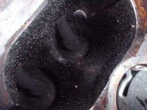
Cause: Carbon deposits on the intake valves. Deposits cause the air to tumble into the combustion chamber, and this turbulence causes the air/fuel mixture to be unevenly distributed. When ignited, the flame front can be erratic, leave unburned fuel and create hot spots in the combustion chamber.

When the early direct-injection engines hit the three-year or 30,000-mile mark, some developed driveablity problems due to carbon buildup on the necks of the intake valves.

In the late ‘90s and early 2000s, TSBs related to carbon deposits on the valves were few and far between. There are three reasons why direct-injection engines are more prone to carbon deposits, one of which is unique to direct injection, while the remaining two are also problems for port fuel injection but are made worse by direct injection.

The main reason is that fuel and added detergents are not hitting the back of the intake valves. By injecting the fuel directly into the cylinder instead of at the back of the valve, the gasoline and detergents can’t clean the valve and port.

Second, leaner mixtures and higher combustion pressures can make the problem worse over time. A direct fuel injection motor produces more energy from a given amount of fuel and air than a port fuel injection engine. Today’s engines operate on a ragged edge between optimal efficiency and a misfire. There is not much room for error, like hot spots in the combustion chamber or a worn spark plug.

When a hot spot or sub-optimal flame front is created due to turbulent air, the amount of unburned fuel in the combustion chamber increases. When the valve opens during the intake stroke, it might come in contact with these byproducts, and, unlike the exhaust valve, the gases passing by are not hot enough to burn them off.

Third, the intake valve goes into the combustion chamber, regardless of whether it is port fuel injected or direct injected. When it does, for that small period of time, the valve is exposed to combustion byproducts that can stick to its neck. If the previous combustion cycle was less than optimal, the intake valve is exposed.

Some direct-injection vehicles with variable valve timing can expose the valve to combustion byproducts as the valves adjust, which creates a scavenging effect to either pull or leave behind a small amount of exhaust gases in the chamber to control NOX emissions. Also, some turbocharged direct-injection engines will leave the intake and exhaust valves open at the same time in order to keep the turbo spinning to reduce lag.

Problem Vehicles: Some direct-injection engines have bad timing. The modern engine typically has variable valve timing and even cylinder deactivation. The engine management system can control when, how long and, in some cases, how deep the valve goes into the combustion chamber. If an intake valve is dropping into a combustion chamber with combustion byproducts or unburned fuel, the valve might be exposed to the precursors that cause carbon buildup.

Positive crankcase ventilation (PCV) systems are sometimes blamed for leaving an oily film on the intake valve that is then baked into carbon. Some blame the valve overlap during the intake stroke that eliminates the need for an EGR valve. Some even have cited cylinder deactivation modes that can create positive pressure.


VW-Carbon-deposits-1Solution

There are several fixes available to solve carbon buildup problems.

The first is preventive maintenance. Scheduled oil changes can keep the camshaft actuators working in optimal condition to control the exposure of the intake valves. Spark plug replacement can reduce the amount of unburned fuel in the combustion chamber that can stick to a valve. Fuel injector cleaning can help injectors maintain the correct spray geometry to prevent hot spots.

But the number one method for preventing a carbon buildup problem is updating the engine management software. New software can reduce carbon deposits by reducing the exposure of the valves to conditions that cause carbon buildup by adjusting valve and spark timing.

Don’t assume that you will find a TSB saying that a reflash of the ECM will correct a carbon buildup problem because most of the updates will be contained in normal housekeeping that may never mention a problem. You may even have to check the OEM’s website to see if the vehicle has the latest version of the software.


Ford EcoBoost EngineWorst Case Scenario

If the vehicle has reached the point where the deposits are affecting performance, you might be able to remove the deposits with a chemical cleaner injected into the intake. This might work to alleviate problems or become a recommended maintenance item for owners with direct-injected vehicles.

Another option is more invasive and requires removing the intake manifold and removing the deposits with brushes or a sand blaster. This can be costly and not the most profitable job for your shop to take on.

Categories
Uncategorized

Pushrod Failures

1. What are the biggest challenges that face today’s competition pushrod maker?

“Racers seeking to exploit every tiny advantage tend to select lighter and lighter weight oils, many of which are impaired or even deficient in lubricity at high loads and high revs. Also, installing pushrods positioned between lifters and rockers with contact surfaces rougher than 1Ra expose the pushrod ends to severe abrasion. For example, a rocker arm adjuster ball with a rough, hard contact surface can act like a file. Plainly, it’s prudent for the engine builder to inquire about the surface finishes of the parts that operate in conjunction with the pushrods.

01-RadCupVCup-300x266“Another factor that leads to premature failure occurs when pushrod balls are bound in tight cups. It’s imperative they have sufficient operating clearance. A further problem arises when you set the ball end of pushrod in a V-cup. The V-cup presents a very narrow contact seat which significantly increases the loading on the pushrod ball end. If its seat is heat treated to a very hard condition, it will eventually pound its V-shape into the pushrod ball. Much more desirable is to set the pushrod ball end in a radius cup and reduce the point loadings.

“Recently, I was reminded by Jon Kaase, the race engine builder, of the severe environment in which the pushrod operates. ‘Assume,’ he said, ‘you have an open spring pressure of 1,400lb and a rocker ratio of 1.9:1, therefore, the loading on the pushrod equates to around 2,660lbs. This is then transmitted through the tiny area of the pushrod ball. If the surface area of a V-cup is 100th of a sq. in., the loading could be somewhere around 300,000psi!’

“In addition to these loadings, increased rocker ratios and engine revs further increase surface speeds on the ball ends.”

2. How long do pushrods last in racing engines?

“In Sprint Cup, the top teams might use them only once or twice and then switch them to their Busch Series engines. Other Cup teams will run them much longer. In NHRA Pro Stock, most of the teams will run them until they show signs of wear. The same is true in Top Fuel and Funny Car, except those pushrods might show signs of discoloration on their ends instead of wear. If they begin to turn blue from excessive heat, it’s time to replace them. In short track oval racing, engine builders will use the same pushrods for several seasons—often six to eight thousand laps—providing they are not bent and show no signs of wear.”

02-0081cuLr-300x1673. What percentage of your pushrod business is racing?

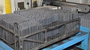
“Probably ninety percent of our production is devoted to racing. But Trend also produces piston pins and tool steel flat tappets for racing, particularly NASCAR. About one half of our valve train production serves professional race teams; the other half is dedicated to the weekend racers and to the high-performance street users.”

4. Do you make single-piece or three-piece pushrods?

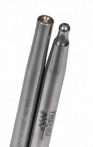
“Trend doesn’t make three piece pushrods, but we do manufacture two-piece. These allow the engine builders to cut the pushrods to length and install the tips as required. Our tips are pressed into the pushrod using a hydraulic press and an installation tool.

But a few years ago, when we introduced a Quickship program, we discovered most engine builders preferred one-piece pushrods. These were finished to size and length—they required no more work—and they’re shipped within 24 hours.”

06-0055-LR-190x3005. From which materials do you manufacture pushrods?

“The biggest proportion is made from chrome molybdenum, a type of alloy steel known as 4130. This material possesses an excellent strength-to-weight ratio and is considerably stronger and harder than standard 1020 steel. Sprint Cup engines use it as do much of Pro Stock and Pro Mod. In contrast, Top Fuel and Funny Car teams use H13 tool steel in solid bar form. The 4130 pushrods are produced from thick-wall tubing. Their hollow center passage is pressurized by oil destined to lubricate the rocker adjuster.”

6. What do you consider the biggest recent failures in valve train?

“As long as racing engines continue to produce more power, failures will soon follow. But failure isn’t too concerning—as long as you learn from it. The most recent troubles we encountered derived from galling in the top cup of Pro Stock pushrods, which we overcame by introducing a bronze insert. When similar troubles afflicted ball-ball pushrods, we succeeded in eradicating it by replacing the top ball with one made of a special self-lubricating tool steel.”